1966 Carlsbro CS40
Refurbishing a beautiful vintage PA amp
Note: This page is a work-in-progress as this refurb is in progress. With that in mind, some details/info might change as work progresses.
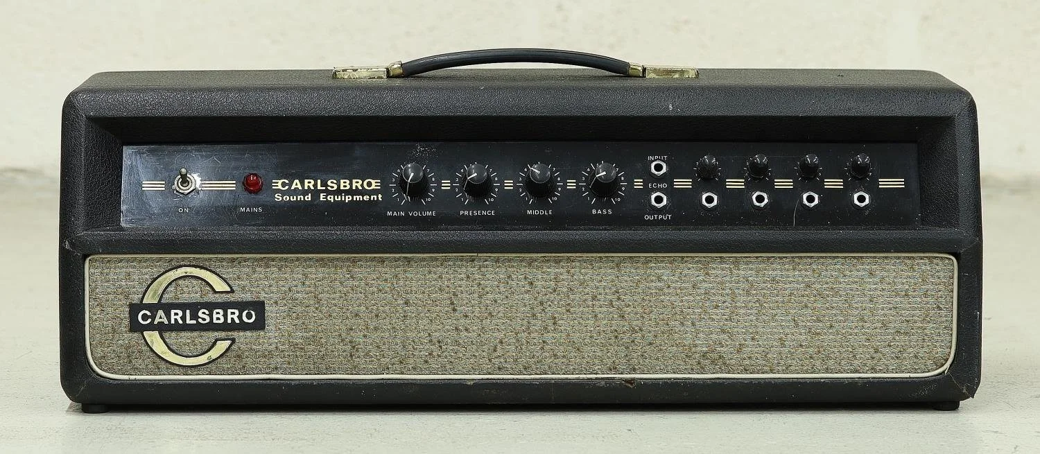
1960’s Carlsbro CS40 - PA
This lovely creature, which I’m currently refurbish, ising an early serial number (SN-465 to be exact) ‘CS40 - PA’ amplifier from the UK company Carlsbro .
From other CS40’s I’ve found online, the serial number puts it as built in 1966, though I’m hoping I can get a more accurate date from some of the components inside it.
It has four inputs, each with their own volume/gain control, a very rudimentry ‘echo’ send and return, Bass, Middle and Presence (Treble) controls and a master volume.
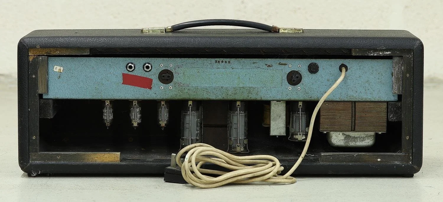
Look at those lovely chunky transformers
It’s ‘upside-down’ style, with incredible (and heavy) lay-down transformers, which are similar to the ones in the Marshall JTM amplifiers of the time.
The preamp is powered by two 12AX7/ECC83 triodes, with another 12AX7/ECC83 for the LTP phase inverter. Power amplification is through two EL34s in a push-pull arrangement, and to cap it off, a GZ34 rectifier tube providing the DC.
History note: This and amps a little later in this series are quite often labeled as ‘CS40 - PA 60’ or ‘CS40 - 60’ (for guitar). The ‘60’ I’ve always taken as referring to the output wattage. However, I think this early version is actually just a ‘CS40’ or a ‘CS40 MK1’. This one should push out around 40 watts, but slightly later builds switched to a newer design, swopping the valve rectifier for diode rectification & changed the power tube biasing to fixed bias, which probably pushed the output to 50w-60w. Hence the ‘CS40 - 60’. The next series was the CS60, which had a diffent style altogether.
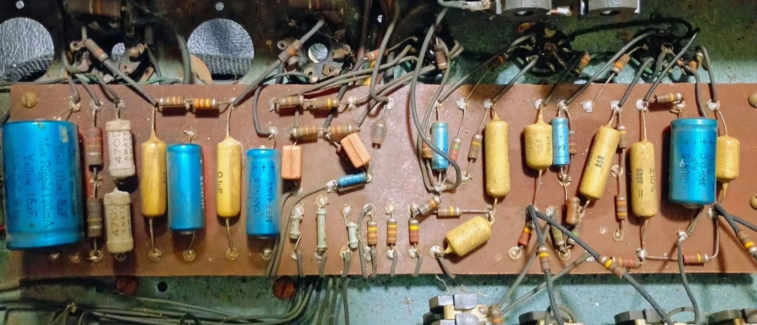
The internals
The internals are handwired on an eyelet board, as most UK amps on the time the components were good quality using Hunts electrolytic capacitors, Mallory mustard caps, & some interesting pinky/orange film capacitors in the LTP. Resistors are for the most part carbon composite, with some wire-wound ones where there’s more power handling needed.
The insides were suitably filthy, looking like it had been the PA in a working mans club for most of it’s life, so the first thing was giving it a good clean with the old cotton buds, alcohol and toothbrush.
Incidently this led to our most viewed and commented on Facebook post, which was unexpected. It was a semi-piss-take post pointing out the sheer inanity of polishing capacitors with cotton buds. However it seemed to strike a chord with quite a few people around the world.

Eh up, our Deidre. What time’s Slayer on?
Before clean

After clean
Checking & testing the components came up with the usual suspects. The main electrolytic filter caps were starting to leak, and most of the others on the board were bulging/leaking.
The Carbon Comp resistors were a mixed bag. I’ve had other vintage amps where 90% of the CC’s were still spot on, however this time I reckon I’ll need to replace about 25% of them as they’ve drifted way out of spec.
Unfortunately the potentiometers didn’t test well, I’m hoping that a good clean and lube might sort them out, otherwise it’s going to be quite hard to source the same size (and quality) nowdays.
Layout
The fun part, however, has been trying to find an exact schematic for this design. There’s a few around, but whilst each one had similarities, none were an exact match. So before taking it apart I created one specifically for this version.
CS40-PA layout. Professionally drawn with crayons.
Technical bits
So to get into the technical nitty gritty. The amp consists of:
2x 12AX7 in the premap
12AX7 LTP phase inverter
2x EL34 in push-pull
GZ34 rectifier
Power transformer with 200V, 225V, 250V input windings, centre tapped 350V output, 6.3V heater & 5.3V heater (for the GZ34) outputs.
10H choke
Output trans with 15R, 7.5R & 3.75R windings
Input stage (V1b & V2b)
The first stage is a mixing stage for the four inputs, using 1 half of each 12AX7 (2 inputs per half). The triodes are biased using the old-school contact/grid leak method, using 3.3Meg grid leak resistors with the cathodes are connected straight to ground.
The plate voltage in this stage is low, around 70V-80V, so we’re not looking at much headroom especially as the biasing method doesn’t deal with large signals well (see note below).
To prevent overloading the stage, the designers have applied some hefty local negative feedback through 220k resistors from the plate to the grid, so the first stage actually doesn't add any gain.
Tech note: Contact biasing works by the natural grid current of the tube flowing through a larger than normal grid leak resistor to establish a small, steady negative bias voltage (around -1V) on the grid. This gives the grid enough negative charge to work, however with large input signals the built-up bias can struggle to recover, resulting in asymmetric clipping and crossover distortion. For a more detailed explanation have a read on the ampbooks site.
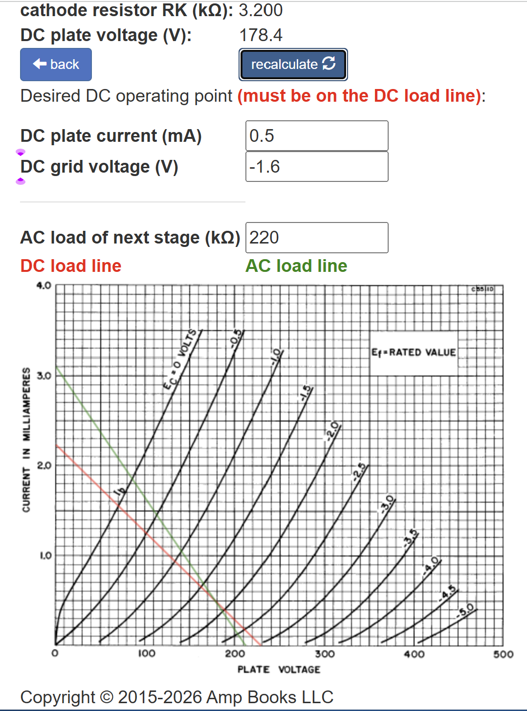
Gain Stages (V1a & V2a)
The other halves of V1 and V2 are used as the gain stages positioned either side of the tone stack.
They’re both cathode biased with a 100k plate resistor, a 3.3k cathode resistor, and a 64uF cathode bypass capacitor.
The DC voltage is low at 150V (though later versions increased this to ~180V), which is around 50% of a ‘normal’ guitar amp gain stage (typically 300V to 350V). Combined with the cold bias (-1.6V), gives about 1V of headroom on the negative cycle.
However, with the ‘zero gain’ input stage, even if all four inputs are receiving a 250mV peak-to-peak signal the combined signal into the pre-tone stack grid is around 275mV, which is safely under clipping.
The cold bias should also give the signal a bit of asymetrical compression, providing some nice 2nd order harmonics.
Gain #1 → Tone stack → Gain #2
As can be seen below the signal comes into the first gain stage fairly flat (light blue), has a little treble roll of after the triode (pink), and then comes out of the tone stack a bit more shaped (green).
The post-TS gain stage rolls off a some of the bass from about 100Hz (blue), & then the coupling capacitors and volume control remove some of the treble above 10kHz.
The final result (red) is a bass hump at 200Hz, a mids scoop at 1kHz, & the treble rising from 2kHz with a peak at 10kHz about 5dB higher than the bass.
Green: Post-TS gain stage output
Blue: Post-TS gain stage coupling cap
Red: After volume control @50%
Light Blue: Pre-ts gain stage input
Pink: Pre-ts gain stage output
Yellow: Tone stack output
Tone stack

The tone stack is a funky James style with an added mids control.
The Bass and Mids pots are double the standard values at 2.2 Meg, with the equivilent decrease in the capacitor values. This reduces the insertion loss slightly, which could be one of the reason the designers chose those values, given the lowish input signal.
EQ sweep/range
Overall the tone stack gives a pretty good amount of control with a lot of range over the bass - around 12dB at 80Hz, 8dB at ~800Hz and around 4dB at 4kHz and higher.
Sweepity-sweep
Bass
The bass control is fairly isolated, and on it’s own has a good range of around ±8dB at 80Hz, with most of the action happening below 200Hz.
Bass sweep. Mids and treble set at 50%
Treble
The mids and treble (presence) controls are very interactive. The treble control has two points of focus, the upper mids/lower treble and mid-high treble.
As the treble is increased, the volume change pivots around 4kHz giving an increase of about 1dB at 10kHz. However, at the same time, the mids scoop is deepened and the frequency is shifted highwe, with a max drop of around 2.5dB in volume and a shift n the bottom of the scoop from 800Hz to 1.2kHz.
Treble sweep. Bass and middle set at 50%
Mids
The mids control has a similar effect as the presence, except focusing on the lower mids and treble. As the control is decreased, the mids scoop moves down in frequency, from 1.5kHz to 500Hz with a corresponding drop in dB of about 6dB. The bass is also shifted & reduced, with the bass hump shifting from 200Hz to 80Hz, with a drop of about 4.5dB.
As the lower mids are rolled off, the treble pivots around the 4kHz point, and increases to a max of ~2.5dB at 10kHz.
Mids sweep. Treble and bass set at 50%
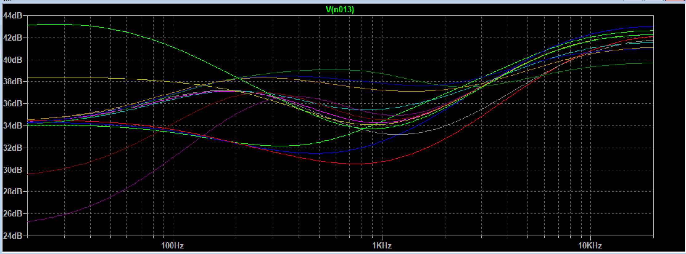
Treble & Mids
Combined, the middle and presence controls give a wide scope. The graph below shows the range with the mids control at 1%, 50% and 100%, and then the treble control at 1%, 50% and 100% for each of those settings.
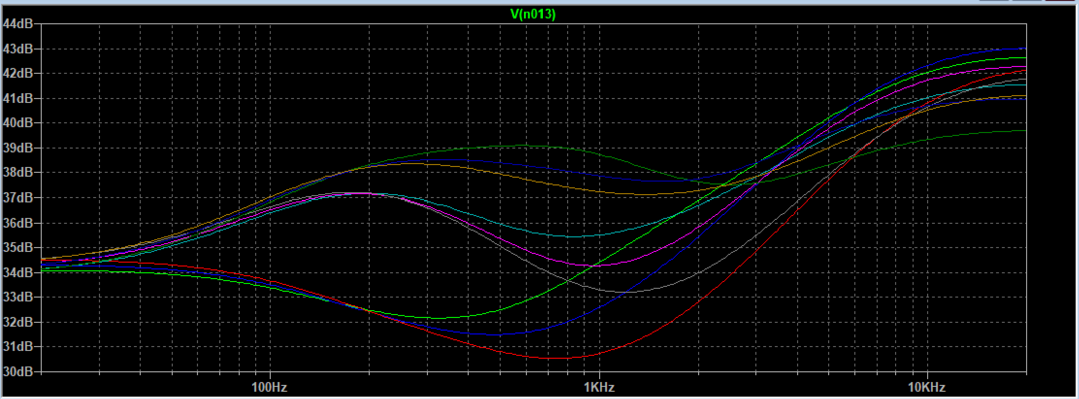
Mid sweep at 1%, 50%, 100%, plus treble sweep at 1%, 50%, 100%
More to come as I dig deeper into this rare old amp!